About transistors - Part 7 : cascading structures
Combine the building blocks you learned about and make powerful amplifiers !
Combine the building blocks you learned about and make powerful amplifiers !
Today, we're gonna build a really high gain amplifier ! And when I mean really high gain, it will have a bit of everything we've learned before to achieve that.
Basically, every structure we've seen before has either a voltage or a current input, and the output is also either a voltage or a current. Every structure has its own relationship between output and input with a function f : OUT = f(IN). Actually, these structures are voltage or current sources that are controlled by a voltage or a current. Seems easy, isn't it ? Well, there are a few things to keep in mind ! We usually want to have the best possible circuits. That means you want the less loss possible when interfacing circuits.
A voltage generator is just a perfect voltage source followed by a resistance is series - this is in fact the generator output impedance. To have the less loss possible, it should be zero. When applying a voltage to a circuit, zero loss is achieved with an infinite input impedance. In all the other cases, the output impedance of the generator and the input impedance of the following circuit form a voltage divider, and the voltage drops by a factor of Zin/(Zout+Zin).
The same thing happens with current ! A current generator is a perfect current source with a resistance in parallel, which is also its output impedance. We want all the available current to go to the next circuit, so no current should flow into this resistance, hence the need of an infinite output resistance. However, when you want current to go through a circuit, it should accept all the current available. The circuit should have zero input impedance. In all the other cases, both impedance create a current divider and the current going into the driven circuit drops by a factor of Zout/(Zin+Zout). Yup, it works exactly the other way as for voltages !
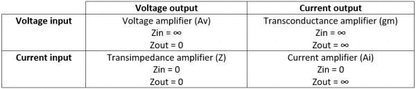
All the structures we've seen fall into four categories, depending of their input and output. They are Voltage or Current Sources Controlled by a Voltage or a Current. Hence the name CCVS, VCVS, CCCS and VCCS you can see in some websites, standing for Current Controlled Voltage Sources, etc... You can sum up the ideal properties of these types of circuits :
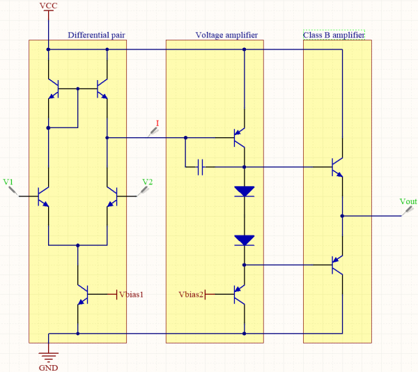
It is pretty straight forward to use the circuits we've seen. A common-emitter amplifier is just a transconductance amplifier and its load converts its current output into a usable voltage for any other voltage amplifier connected to it. You can cascade a transconductance amplifier with a current amplifier to have more gain, or two voltage amplifiers for example ! The circuits are arranged in what's called compatible associations : the output of each is the same type as the input of the following circuit. All the other arrangements are called incompatible associations. Fortunately, it doesn't mean the arrangement doesn't work, and it can in fact dramatically increase the gain of the whole circuit ! Let's examine the following circuit as a proof of concept.
We want a voltage amplifier witgh high gain and differential input. To deal with the differential input, we can use our most advanced differential pair from part 6 of the tutorial series, which is a transconductance amplifier of gain gm. However, we've seen that we can put a common-emitter voltage amplifier right after to increase the voltage gain of the whole, because the current of the first stage goes through the resistor Req made of the input impedance (hfe+1)*rd of the common-emitter in parallel with the Early resistance r0a of the differential pair. Basically, it can go as high as a thousand ! But we can increase the voltage gain further by using an active load for our common-emitter, effectively increasing its own gain up to the ratio of the active load's own Early resistor r0b and rd. The last stage is only a class B amplifier, which reduces the output impedance near zero and has no effect on voltage gain. It is useful only if we want to drive heavier loads. The diodes are biasing the class B amplifier, and the cap is here for stability. It is called a compensation capacitor, and its value is low but increased because of the Miller effect ! Without it, our circuit would oscillate because of its high gain, and its presence is required even though it reduces the bandwidth of the amplifier down to a few decades. The whole gain of the amplifier is actually sooo high it can reach 100 000 easily, and there are a lot of possible improvements on the circuit to make it even higher !
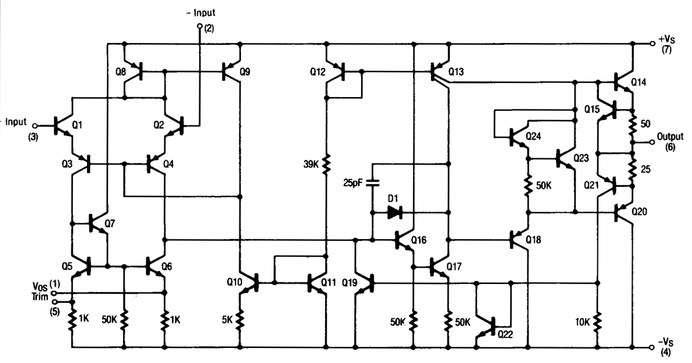
Well guys, here it is, the end of our BJT transistor exploration... We've come accross the most basic structures to have such a high gain amplifier. This is the basis for an operationnal amplifier : differential input, high gain and low bandwidth, almost infinite input impedance and almost zero output impedance. This is near the most perfect amplifier we can have in electronics and this type of circuit is used absolutely everywhere since its invention. The circuit shown here is here to give you an idea of "how it works in the inside", and I will make a tutorial series talking about opamps soon !
Thank you very much if you read everything, if you have any questions feel free to ask ! 
Sería genial información de los amplificadores tipo cascode
http://everycircuit.com/circuit/4648837736824832
Rss feed of the article's comments