About opamps - Part 1 : the ideal opamp
Hi hate this website, so buggy !
Hi hate this website, so buggy !
Welcome to this new series of article ! You may have read the previous one about transistors. If you didn't understand everything, don't worry ! Opamps are a whole new deal compared to transistors, and work completely differently. In fact, opamps are made using the transistor circuits of the last tutorials.
Operationnal Amplifiers, also called opamps or AOPs, are differential voltage amplifier with high gain. It means they amplify the difference of voltage between there two inputs. One is called the non-inverting input, the other input being the inverting one. The symbol of an opamp is a triangle showing all the different terminals.

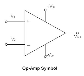
Most of the time, in circuits, the power supply inputs are not shown. However, keep in mind the output of the opamp cannot go higher than the positive supply, and cannot go lower than the negative supply. In fact, a lot of opamps cannot even go near them, and only "rail-to-rail" opamps are able to reach their power supply.
When I talk about high gain circuits, I do not mean it like in high gain guitar amplifiers. What I really mean is that opamps can have a voltage gain from 100dB to 120dB. Yes, it means a 1uV signal is amplified up to 1V, and a 1V signal should be amplified up to 1kV. Ten times higher than the RMS voltage in your electrical outlet ! In practice the opamp will just clip and its output will stay around the positive or the the negative supply. If the inverting input voltage is higher than the non-inverting input voltage, the output of the opamp will clip to the negative supply. If the non-inverting input is higher than the inverting input, the output will clip to the positive supply. This behaviour is obviously non-linear, just like an electronic comparator. However, opamps are really meant to be used in linear application : amplification, filtering...
There are three rules to remember everytime you meet an opamp in a schematic. These rules apply to the ideal opamps but are perfect to understand circuits :
- If the opamp is working as a linear amplifier, the voltage between its input is zero. This means V1 = V2. Depending on the circuit arrangement, the output of the opamp will always try to make this equation true.
- If the output cannot move so that V1 = V2, the opamp is clipping and the output is either equal to the positive supply or to the negative supply.
- In both case, the current going into the inputs is zero.
Let's examine both linear and non-linear cases with a small circuit : one opamp and two resistors ! At first glance they look pretty similar and you may want to say they are the same, but pay close attention to the inputs of the two opamps shown. On the left, the input is sent to the non-inverting input of the opamp and the output is looped back at the inverting input through a resistor voltage divider. On the right, the input is sent to the inverting input, and the loop goes through the positive input of the opamp ! Two similar configurations but not the same use at all !
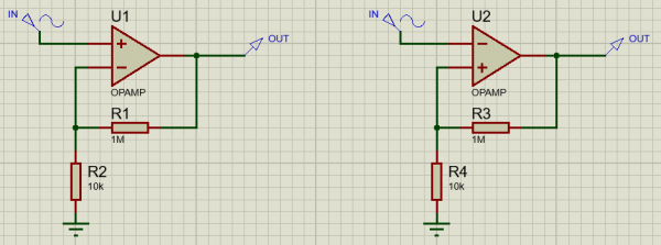
First, the circuit on the left. Input voltage Vin is applied between ground and the non-inverting input. Because the opamp will always try to have the inverting input at the same potential, it means we have to get a voltage equal to Vin across resistor R2. In order to achieve that, hence a current of I = Vin/R2 flowing through R2. This current has to come from the opamp output, as we said no current will ever go through any input of the opamp. Hence, we should also have I = Vout/(R1+R2). Finally, we can now calculate the voltage gain Vout/Vin by dividing the two equations and solving. We get Vout/Vin = (R1+R2)/R2 = 1+R1/R2. We have found a constant gain, the opamp works as a linear voltage amplifier ! This building block is at the heart of the MXR Microamp pedal.
However the circuit on the right is not at all an amplifier, and is more commonly known as a Schmitt Trigger. This circuit is in fact a latching circuit for detecing a voltage above or below a fixed treshold. A lot of variant exist but here is the simplest one. Technically, we should use a comparator instead of an opamp but for slow signals (meaning under 100kHz or so), an opamp is usually good too. Let's say we apply a voltage Vin to the inverting input. Because the opamp inputs were sitting at zero potential, we now have a higher potential at negative input than at the positive input, the opamp output will go more negative trying to get both input at the same voltage, but the non-inverting voltage will just fall down more and more until the opamp clips its output to the negative supply voltage V-. To get the output back toward zero, the input voltage has to get lower than the output voltage, attenuated through the resistor divider. That's to say we need to have Vin < [R4/(R3+R4)]*V-. When that is the case, the opposite effect happens : the output voltage will get too high and we will have the output voltage Vout sitting at the positive supply voltage V+, with a treshold of Vin > [R4/(R3+R4)]*V+ this time. We have an inverting latch which is triggered by crossing through two different treshold : one for the negative and one for the positive voltage swing. That is basiccaly what a Schmitt Trigger is : a latching logic gate with integrated hysteresis. This is of course a highly non-linear circuit which could sound awesomely weird in a guitar pedal !
Take your time to read through our series of articles or go to a project if you want to see some practical realisations ! See you next time !