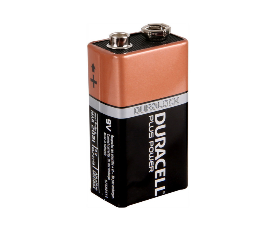
What is going on with positive ground ?
Old guitar pedals use a reversed 9V battery... But things have changed since 1960 !

Old guitar pedals use a reversed 9V battery... But things have changed since 1960 !
Fellow pedal friends, I am seeing a lot of people asking about positive ground pedals, how to invert 9V to -9V to match the original circuits for Fuzz Faces and Rangemasters... I think there are a lot of confusion about PNP transistors and what are called positive ground and negative ground pedals. Let me explain quickly why there is no such thing as positive ground !
Most recent guitar pedals use the standard 9V Boss-style power supplies. These pedals are using a voltage between 0V and 9V to work, and the ground is tied to 0V. However, when you look at older pedals (Fuzz Face, Tone Bender, Rangemaster...), all of them use a reversed 9V battery to get powered from -9V to 0V, with ground still being tied to 0V. Now, you can see why the common names "negative ground" and "positive ground" come from. In the first case, ground is simply the lowest voltage the circuit uses, and in the other case, it is the highest. In both case though, ground is 0V. Period.
Why can't I use a 9V power supply and just reverse the wires from 0V to 9V on my PCB then ? Well if you do so, you're sending 9V instead of ground. That also means you're having 9V on the enclosure, the sleeve of your jacks, your guitar... And that would be fine honestly, except for one thing ! Your amp or your next guitar pedal has its jack sleeve connected to their ground, and if your power supplies or not fully floating and isolated, that means you're having a short-circuit. Which you can guess, can burn your power supply. There is one way to make these "positive ground" pedals work with a standard power supply though, but you need to understand the circuit first. If you're still unsure about how transistors work, I guess you can read this unbiased and excellent series of articles.
First let's talk again about PNP transistors. Back when the Fuzz Face was designed, PNP germanium transistors where much more readily available than NPN equivalents, and cheaper. Engineers were used to use them in their circuit and it was easy to use them with batteries as well. You can stack batteries to get both 9V and -9V, or having -18V supplies, basically whatever you want. There wasn't any standards about how to power the pedals and obviously Boss wasn't born yet. Transistor had their emitter tied to ground in amplifier circuits, both NPN and PNP - I guess it was because "they work in reverse" and engineers were used to vacuum tubes ? PNP transistors then had their emitter tied to ground, and needed a negative voltage to work. Fortunately, they also work if you tie their emitter to 9V, for example and use ground as the "more negative voltage", hence effectively powering them from a standard 9V power supply. What I am saying is PNP transistors don't care if you power them from -9V to 0V, or 0V to 9V : as long as the voltage difference is the same, they will work the same. The following picture sums it all. The left "positive ground" circuit is exactly the same as the right "negative ground" circuit.

So, how can I build one of these old circuits to work with more modern power supplies ? Well, you can just change the voltage in all the circuit between the input and output coupling caps. These are used to remove any DC offset anyway ! Let's have a black box approach. Just isolate your input, output passive circuits and shift the voltage up by 9V for all in-between components. Note that you do not need to reverse any component polarity there.

I hope this article was useful ! Leave a comment if you have any question - I'll happily answer it.
Hi!
Great article, but I don’t see the picture that compares the positive and negative ground circuits. Just wanted you to know in case you didn’t know it was missing. Thanks again!
Rss feed of the article's comments