About transistors - Part 2 : the bipolar transistor
Let's continue our journey in the world of semiconductors !

Let's continue our journey in the world of semiconductors !
Welcome back ! I hope you read the previous article, you will need it to understand today's course. Let's remember what we saw together last time !
When the voltage accross a diode is positive enough, (higher than Vd, the treshold voltage), the diode conducts the current exponentially with voltage. If the voltage is less than Vd or negative, the diode blocks most of the current. Because it is not perfect, there will always be a little current flowing in the diode when it is reverse biased.
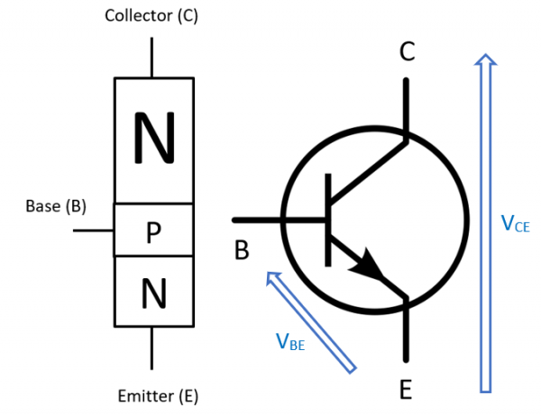
Let's imagine we take our diode, which is a PN junction, and we put another N-type semiconductor on top of the P-type. We now have a weird semiconductor sandwich made of two N-type material with a P-type between them. This is our transistor ! Obviously, a NPN transistor. By putting a N-type semiconductor between two P-type, we get the exact opposite : a PNP transistor. They both work the same way, so I will only detail how a NPN transistor works.
A transistor is made of two PN junctions connected so that they share one electrode. This is why you can see on many websites that "a transistor is just two diodes back to back". THIS IS NOT TRUE ! This is just a reminder of how a transistor is made, but you will never get a transistor by putting two diodes back to back !
How does a transistor work ? Well, a bit like a diode, but it has three electrodes !

Let's say you connect a battery at the two N-type poles of the transistor, so that Vce is made a few volts positive. By doing that, the electrons in the top N-type material is attracted toward the positive pole of the battery, and so are the bottom N-type electrons. However, because there are holes in the P-type junction, those electrons just stay in the bottom part.
When the voltage Vbe is made just a touch higher than Vd, the bottom junction behaves like a diode and current starts flowing from the base (B) to the emitter (E). Remind that electrons flow in the opposite direction of the current : from emitter to base. However, because there is a higher voltage at the collector (C), part of the electrons go through the top N-type junction instead of going into the base ! There is a current from collector to emitter ! If the P-type junction is made really small and the top N junction is really doped with electrons, there are a lot more electrons going into the collector than into the base. What does that mean ? Our transistor commands the current from collector to emitter with the voltage Vbe. Here it is, our basic idea of an amplifier ! Moreover, because of the properties of the bottom PN junction, we already know that the current in the transistor follows the Shockley exponential Equation and that voltage Vbe stays more or less constant.
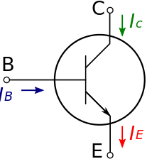
Ouch ! That's a lot of things to understand, grab a cup of tea and take your time to read and understand the last paragraph. What I say is just that the voltage Vbe controls the emitter current Ie through the transistor, following the exponential law. Please note we also have an equation between the currents flowing in the transistor : the emitter current Ie is the sum of the collector current Ic and the much lower base current Ib : Ie = Ic + Ib.

Base current is a flaw of the transistor, and not something you should rely on to run calculations. A lot of websites call transistor a current amplifier. THIS IS ALL WRONG when talking about small power ! A transistor is a tranconductance amplifier, converting voltage into current. Technical documentation will give you an idea of the "quality" of the transistor with the parameter beta, or hfe. It represents the current gain of the transistor : hfe = dIc/dIb. Never in the world should an audio engineer design a guitar pedal or a preamp using this parameter as the base for his calculations. The reason is simple : hfe varies with temperature, the actual value of Ic - meaning non-linearities - and is highly variable from a transistor to another. Yes, even when it is the same model ! This parameter is highly unreliable for design in our guitar amplifiers, but it comes to a use for some calculations somehow and for power transistors.
Wondering how it works with PNP transistors ? No problem ! Just switch the sign of every current and voltage, and you get the exact same behaviour ! In a few chapter, we will analyze how a simple PNP treble booster works as a practical exemple of amplification.