Circuit Analysis : Fulltone's OCD
The made in USA boutique pedal became a new standard for overdrive !
The made in USA boutique pedal became a new standard for overdrive !
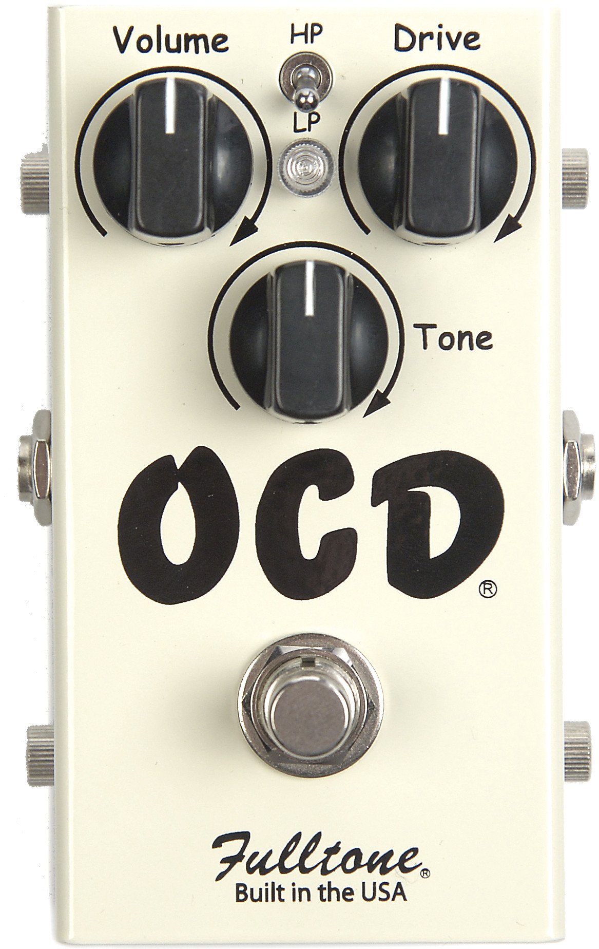
First created in 2004 by Mike Fuller (Fulltone), the OCD was a circuit giving more dynamics to the sound of your guitar while letting you crank up the gain. Even more dynamic than the Boss BD2, the OCD uses MOSFETs to clip the signal with a sensitivity close to what you can feel when playing a tube amplifier. Lots of guitarists adopted that pedal since its invention and even though many versions exist, they only differ by some component values and do sound quite close to each other. More recent versions add a 1N34A Germanium diode in the clipping section for asymetrical clipping, as well as better power supply filtering. The v2 has some more in-depth changes.
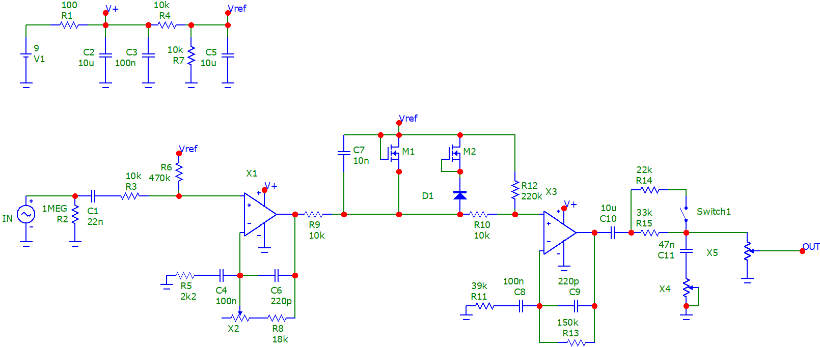
The OCD features a TL082 dual opamp chip used as non-inverting amplifiers, with a 2N7000/1N34A clipping stage in-between the gain stages. A passive "treble bleed" tone stack together with the High Peak/Low Peak switch gives some control over the high frequencies.
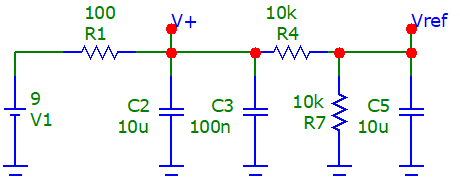
The circuit is designed both for a 9V battery or a 9V center negative Boss-style power supply. The circuit can also be powered up to 18V. R1 and C2/C3 filter the power supply to remove the noise. Electrolytic capacitors are known to have resistive and even inductive effects at higher frequencies - using a low value ceramic or film cap in parallel helps to filter the noise further up the frequency range. R4, R7 and C5 form a voltage divider providing a reference voltage of half the power supply voltage (4.5V for a 9V power supply).
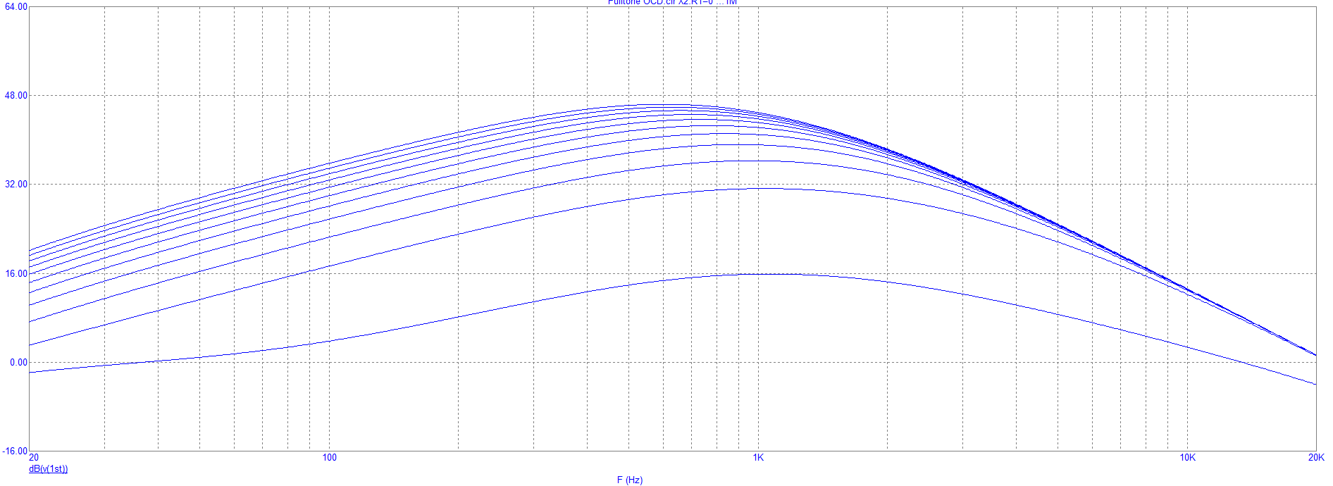
Let's study the first gain stage, between the input and the RC network composed of R9 and C7, disconnecting the rest of the circuit. We find the usual 1M resistor (R2) to give the input cap C1 a voltage reference to ground. R3 limits the current going to the opamp while R6 biases it to Vref. Input impedance is about 330k. The ratio of the gain pot (1M) + R8 and R5 sets the maximum gain of the circuit. C6 limits the frequency response and stabilizes the gain stage. C4 limits the amount of bass frequencies getting amplified. High frequencies are further reduced by R9 and C7. R9 also limits the current going to the clipping stage. The simulation gives the following frequency response, with the gain pot varying.
The signal then goes into the clipping stage, built with a 2N7000 in parallel with another 2N7000 and a 1N34A germanium diode. In this configuration, both MOSFETs are used a slow-slope diodes, which gives a smoother sound compared to diodes - even though the circuit is hard-clipping the signal ! Here are the voltage transfer curve (plotting Vout function of Vin) and the transient analysis of the circuit. We can definitely talk about hard clipping here, but the edges are smoother than what you get on the Boss BD2 for example.
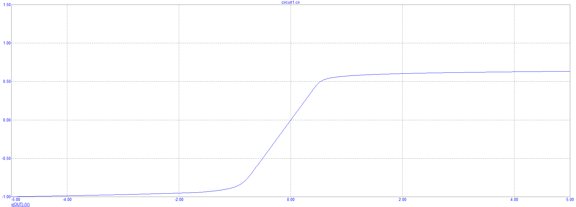
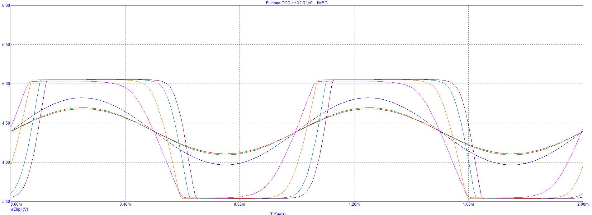
We can also see on the last graph that the voltage cannot rise above +5V, and almost reaches -3.5V, which is asymetrical clipping.
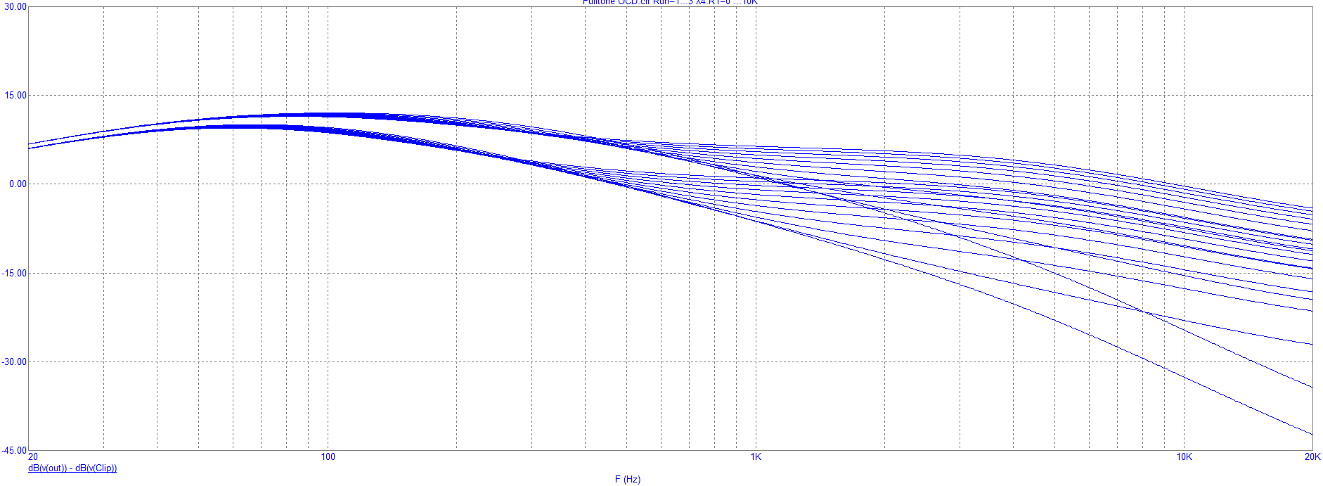
The last gain stage is the same type as the first one, but its gain is defined by the two resistors in the feedback loop. The following circuit sends the treble frequencies through the 10k pot X4 and cap C11 to ground, filtering the high frequencies. The volume and bandwidth are also affected by the HP/LP switch, which parallels resistors R14 and R15. When varying the pot and the switch, we get the following frequency response.
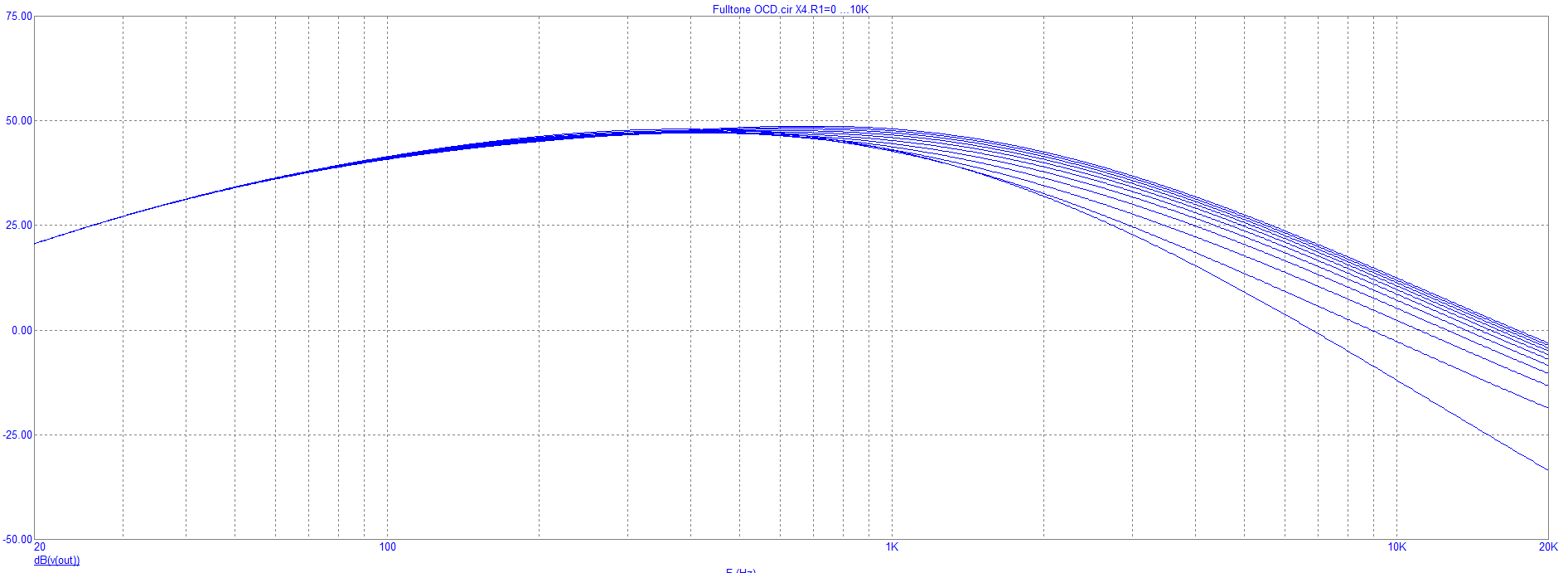
Taking into account the whole circuit, here is the global frequency reponses when varying the tone pot. The OCD emphasizes the mids to be heard in the mix with an overall 50dB of gain. When powering the pedal with and 18V adaptor, the opamps won't get into saturation, leading to an increased headroom.
Here it is, the analysis of the Fulltone OCD ! Really specific saturation characteristics and easier to understand than the Boss BD2. If you have questions or ideas, please let us know in the comment section below !